Science for young minds!

Our ice shelf work is now available in a “young-mind-version” – have your daughter / son / grand children / children of your neighbours / random kids in the street and everyone else with a young mind check it out here ! And have a look yourself too while you are at it! It’s a lot easier to read than the text in Nature – and the illustrations are really cute!

Many thanks to Mirjam and to the two young reviewers (Margarita and Isabel) for making this happen!

New article in Frontiers for Young Minds about ice shelves and warm ocean currents. from: https://kids.frontiersin.org/article/10.3389/frym.2020.00124


Icebergs for children – and everyone else!

I stumbled over this masterpiece on twitter and I thought I’d share it with you: a book for children explaining the origin and fate of an Antarctic iceberg! Illustraed by amazing pieces of art, nicely told, scientifically correct and on top of all freely available at https://joidesresolution.org/activities/iceberg-of-antarctica-book/ !

The author/artist Marlo Gansworthy joined a Polarstern cruise to the iceberg alley a few years back – and now we can all enjoy the result! Download and be amazed together with your children (or on your own!) . You can read her blog from the expedition and find more of her art here!


Beautiful icebergs!

Huge iceberg that we passed on the 3rd of March. Photo: Karoline Viberg

Look at this beautiful iceberg that we passed during our transect to Dronning Maud Land! In Antarctica, icebergs of very different size and shape calve off ice shelves or marine terminating glaciers frequently. Did you know that the largest iceberg  that has ever calved off was 11000 km² big? It is called B15 and broke off the Ross Ice Shelf in 2000. More recently in July 2017, the iceberg A68 with 5800 km² disintegrated from Larsen C in the Antarctic Peninsula. In the Figure below you can see that icebergs from the Antarctic Peninsula drift northward and enter the Antarctic Circumpolar Current –entering our track to Dronning Maud Land.

This plots shows modeled trajectories of icebergs for 1997-2008. Class 5 is the biggest iceberg type and they travel very far! (from Rackow et al., 2017)

Observing icebergs and their drift trajectories on satellites is important to avoid collisions with ships, but scientists also study them because they interact with the surrounding ocean and influence the ecosystem. Surface winds push sea ice towards the iceberg on one side and away from them on the lee side, where a so-called polynya (ice-free area) develops. This has a strong influence on biological productivity and ventilation of the ocean. In addition, iceberg melt increases phytoplankton growth and sea ice growth due to the strengthened stratification. Very big icebergs such as B15 and A68 are studied because they destabilize the grounded ice and accelerate ice loss into the ocean. Why do they break off in the first place, what do they do to the grounded ice? Also, how does the underlying ecosystem react to the sudden income of sunlight after many centuries of darkness? All these questions are important for the Southern Ocean, but very little studied. It is not our aim to study the impact of icebergs, but we still need knowledge about it, because the icebergs have such a big influence on the surrounding water.

Today we passed by B15, which has traveled since 2000 all the way from the Ross Ice Shelf to the Weddell Sea. It has lost big parts of it on the way, but it is still very big. We were waiting outside with our cameras ready to take pictures of it, but unfortunately it was too foggy to see anything. That was too bad…

What happens when a current meets an obstacle? Topographic steering

As long as water depth and latitude stay the same, a current usually happily goes straight forward. However, a large part of what we are doing at the Coriolis tank in Grenoble has to do with what happens to ocean currents when they meet topography, so sea mounts, ridges or troughs under the water, and what happens then is called topographic steering.

Topographic steering basically means that a current will follow lines of constant potential vorticity (ω+f)/H. In this, ω is the rotation of the fluid (more on this here), f is the Coriolis parameter, and H is the water depth. So if a current is flowing  straight ahead (ω=0) in a sea of constant depth, it will stay at the one latitude where it started. If, however, there is a ridge or a canyon in its way, it will try to move such that it either changes its rotation or that it reaches a different latitude so that it stays on a path of constant (ω+f)/H.

What does that mean for our experiments?

In our experiments, we actually change the water depth not only by sloping the floor down into the canyon, we also change it by taking away height from the top by introducing ice shelves.

f in the tank is constant (explanation here), so only ω/H need to be conserved, meaning that the current needs to either follow lines of constant depth, or compensate for any depth change by changing its rotation. I have described in this post what that means for the flow in our tank: We expect — and observe visually (see picture on top of this post) — that an ice shelf that is tilted such that it is slowly decreasing the water depth will force the current down the slope of the canyon, until it reaches the deepest point, turns, and moves up again.

But now Nadine has plotted the actual measured data, and we see the same thing! Below you see a plot of the flow field on a level just below the upper edge of the canyon. I have drawn in where the ice shelf is situated and where the contours of the channel are, and, most importantly, that the flow field shows exactly the behaviour we were hoping for!


The messy flow field where the contours of the ice shelf are drawn in is probably because the data that is being plotted has been calculated from pictures that were taken from above the tank, through the ice shelf, so we don’t have good data in those spots. But all in all, we are very happy! And almost ready to call it a day. Almost ready, except it is still too exciting to think about our experiments… 😉

How we can see vertical slices of the flow field in our tank

We’ve talked before how we use the laser to light up neutrally-buoyant particles on horizontal slices of our tank, but we can actually also do this in the vertical.

This is sometimes very helpful to check whether the particle distribution is still good enough or whether someone needs to go in and stir up some particles before the next experiment.

We are constantly adding water to the tank — how is the water level kept stable?

You’ve probably been wondering about this, too: We have a constant inflow from our “source” into the tank. How do we keep the water level stable?

Worry no more — here is the answer. In the picture above you see Samuel adjusting the skimmer — a sink inside the tank that height is adjusted such that its upper edge is exactly at where the water level should be. So any excess water is skimmed off and drained.

Sounds easy, but it’s actually not — we have a free surface in the tank and we are rotating quite fast, so there is a height difference of almost 10 cm between the center and the outer edge. So a little bit of fiddling around involved…

About the influence of viscosity: The Reynolds number

I read a blog post by Clemens Spensberger over at  a scisnack.com couple of years ago, where he talks about how ice can flow like ketchup. The argument that he makes is that ketchup on your hotdog behaves in many ways similarly to glaciers on for example Greenland: If there is a layer of a certain thickness, it will start sliding off — both the ketchup off your hotdog and the glaciers off Greenland. After most of it has dripped to your shirt or in the ocean, a little bit still remains on the hotdog or the mountain. And so on.

What he is talking about, basically, are effects of viscosity. Water, for example, would behave very differently than ketchup or ice, if you imagine it poured on your hotdog or raining down on Greenland. But also ketchup would behave very differently from ice, if it was put on Greenland in the same quantities as the existing glaciers on Greenland, instead of on a hotdog as a model version of Greenland in a relatively small quantity. And if you used real ice to model the behaviour of Greenland glaciers on a desk, then you would quickly find out that the ice just slides off on a layer of melt water and behaves nothing like you imagined (ask me how I know…).

This shows that it is important to think about what role viscosity plays when you set up a model. And not only when you are thinking about ice — also effects of surface tension in water become very important if your model is small enough, whereas they are negligible for large scale flows in the ocean.

The effects of viscosity can be estimated using the Reynolds number Re. Re compares the effects of the velocity u of the flow, a length scale of an obstacle L, and the viscosity v: Re = uL/v.

Reynolds numbers can be used to separate different flow regimes: laminar flows for very low Reynolds numbers, nice vortex streets for Re > 90, and then flows with a stagnant backwater for high Reynold numbers.

Dependency of a flow field on the Reynolds number. Shown is the top view of a flow field. You see red obstacles and blue stream lines (so any particle released at any point of a blue line would follow that line exactly, and in the direction shown by the arrow heads)

I have thought long and hard about what I could give as a good example for what I am talking about here, since all seems so academic. And then I remembered that I did an experiment on vortex streets on a plate a while back.

Screen shot 2015-02-21 at 4.38.32 PM

If you start watching the movie below at min 1:28 (although watching before won’t hurt, either) you see me pulling a paint brush across the plate at different speeds. The slow ones don’t create vortex streets, instead they show a more laminar behaviour (as they should, according to theory).

Vortex streets, like the one shown in the picture above, also exist in nature. However, scales are a lot larger there: See for example the picture below (Credit: Bob Cahalan, NASA GSFC, via Wikipedia)

vortex-street-1

While this is a very distinctive flow that exists at a specific range of Reynolds numbers, you see flows of all different kinds of Reynold numbers in the real world, too, and not only on my plate. Below, for example, the Reynolds number is higher and the flow downstream of the obstacle distinctly more turbulent than in a vortex street. It’s a little difficult to compare it to the drawing of streamlines above, though, because the standing waves disguise the flow.

2017-09-10-15-16-00

One way to manipulate the Reynolds number to achieve similarity between the real world and a model is to manipulate the viscosity. However that is not an easy task: if you wanted to scale down an ocean basin into a normal-sized tank, you would need fluids to replace the water that don’t even exist in nature in liquid form at reasonable temperatures.

All the more reason to use a large tank! 🙂

Who is faster, the currents or the waves? The Froude number

A very convenient way to describe a flow system is by looking at its Froude number. The Froude number gives the ratio between the speed a fluid is moving at, and the phase velocity of waves travelling on that fluid. And if we want to represent some real world situation at a smaller scale in a tank, we need to have the same Froude numbers in the same regions of the flow.

For a very strong example of where a Froude number helps you to describe a flow, look at the picture below: We use a hose to fill a tank. The water shoots away from the point of impact, flowing so much faster than waves can travel that the surface there is flat. This means that the Froude number, defined as flow velocity devided by phase velocity, is larger than 1 close to the point of impact.

At some point away from the point of impact, you see the flow changing quite drastically: the water level is a lot higher all of a sudden, and you see waves and other disturbances on it. This is where the phase velocity of waves becomes faster than the flow velocity, so disturbances don’t just get flushed away with the flow, but can actually exist and propagate whichever way they want. That’s where the Froude number changes from larger than 1 to smaller than 1, in what is called a hydraulic jump. This line is marked in red below, where waves are trapped and you see a marked jump in surface height. Do you see how useful the Froude number is to describe the two regimes on either side of the hydraulic jump?

Obviously, this is a very extreme example. But you also see them out in nature everywhere. Can you spot some in the picture below?

But still, all those examples are a little more drastic than what we would imagine is happening in the ocean. But there is one little detail that we didn’t talk about yet: Until now we have looked at Froude numbers and waves at the surface of whatever water we looked at. But the same thing can also happen inside the water, if there is a density stratification and we look at waves on the interface between water of different densities. Waves running on a density interface, however, move much more slowly than those on a free surface. If you are interested, you can have a look at that phenomenon here. But with waves running a lot slower, it’s easy to imagine that there are places in the ocean where the currents are actually moving faster than the waves on a density interface, isn’t it?

For an example of the explanatory power of the Froude number, you see a tank experiment we did a couple of years ago with Rolf Käse and Martin Vogt (link). There is actually a little too much going on in that tank for our purposes right now, but the ridge on the right can be interpreted as, for example, the Greenland-Scotland-Ridge, making the blue reservoir the deep waters of the Nordic Seas, and the blue water spilling over the ridge into the clear water the Denmark Strait Overflow. And in the tank you see that there is a laminar flow directly on top of the ridge and a little way down. And then, all of a sudden, the overflow plume starts mixing with the surrounding water in a turbulent flow. And the point in between those is the hydraulic jump, where the Froude number changes from below 1 to above 1.

Nifty thing, this Froude number, isn’t it? And I hope you’ll start spotting hydraulic jumps every time you do the dishes or wash your hands now! 🙂

All pictures in this post are taken from my blog “Adventures in Oceanography and Teaching“. Check it out if you like this kind of stuff — I do! 🙂

The ocean is very deep. It’s also very shallow. On the L/H aspect ratio and the size of the tank.

When we come back from research cruises, one of the things that surprises people back home is how much time it takes to take measurements. And that’s for two reasons: Because the distances we have to travel to reach the area we are interested in are typically very large. And then because the ocean is also very deep.

People usually find it hard to imagine that it can easily take hours for an instrument, hanging on a wire from the ship, to go down all the way to the sea floor and then come back up to the ship again. A typical speed the winch is run at is 1 m/s. That means that for a typical ocean depth of 4 km, it takes 66 minutes for the instrument to go down, and then another hour to be brought back up to the ship. And then we haven’t even stopped the winch on the way up, which we usually do each time we want to take a water sample. So yes, the ocean is very deep!

A CTD coming on board RV Håkon Mosby in 2016 (more on that cruise here)

And yet, it is not deep. At least not compared to its horizontal extent. The fastest crossing of the Atlantic, some 5000km, took something like 3 days and 10 hours. And according to a quick google search, a container ship typically takes 10 to 20 days these days. So there is a lot of water between continents! And it is really difficult to imagine how large the oceans really are.

One way to describe the extent of the ocean is to use the L/H aspect ratio. It is just the ratio between a typical length (L), and a typical depth (H). A typical east-west length in the Atlantic are our 5000 km used above, and a typical depth are 4 km. This gives us an aspect ratio L/H of 5000/4 which is 1250. That is actually a really large aspect ratio — the horizontal length scales are a lot wider than the vertical ones.

Now think about the kind of tank experiments we typically do. Here is a picture of a very simple Denmark Strait overflow experiment (more on that experiment here). You see the tank in the foreground, and a sketch of the same situation on the wall in the background. What you notice both for the experiment and the depiction is that in both cases the horizontal length scale is only about twice as much as the vertical one, leading to a L/H of 2.

This L/H of 2, however, is supposed to represent a situation that in the real world has a horizontal scale of maybe 1000 km and a vertical one of maybe 1 km, which leads to a L/H of 1000. So you see that the way we typically depict sections through the ocean is very distorted from what they would look like if they were geometrically similar, meaning that they had the same L/H ratio, which means that they could be transformed into the real world just by uniformly stretching or shrinking.

Below I have sketched a couple of duck ponds. The one on the left (with an aspect ratio L/H of 1) is geometrically shrunk below: Even though L and H become smaller, they do so at the same rate: their ratio stays the same. However going along the top row of duck ponds, the aspect ratio increases: While L stays the same, H shrinks. This means that the different ponds along the top of the picture are not geometrically similar. However, the one on the top right is geometrically similar to the one in the bottom right again (both have an L/H of 6). Does this make sense?

So in case you were wondering about why we need a tank that has 13 meters diameter — maybe now you see that it allows us to maintain geometric similarity a lot better than a smaller tank would, at least when we want to have water depths that are large enough that allow us to neglect surface tension effects and all that nasty stuff.

More on how Elin actually designed the experiments soon! 🙂

Why we actually need a large tank — similarity requirements of a hydrodynamic model

When talking about oceanographic tank experiments that are designed to show features of the real ocean, many people hope for tiny model oceans in a tank, analogous to the landscapes in model train sets. Except even tinier (and cuter), of course, because the ocean is still pretty big and needs to fit in the tank.

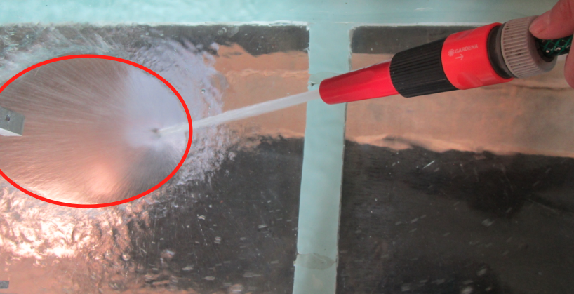
What people hardly ever consider, though, is that purely geometrical downscaling cannot work. Consider, for example, surface tension. Is that an important effect when looking at tides in the North Sea? Probably not. If your North Sea was scaled down to a 1 liter beaker, though, would you be able to see the concave surface? You bet. On the other hand, do you expect to see Meddies when running outflow experiments like this one? And even if you saw double diffusion happening in that experiment, would the scales be on scale to those of the real ocean? Obviously not. So clearly, there is a limit of scalability somewhere, and it is possible to determine where that limit is – with which parameters reality and a model behave similarly.

Similarity is achieved when the model conditions fulfill the three different types of similarity:

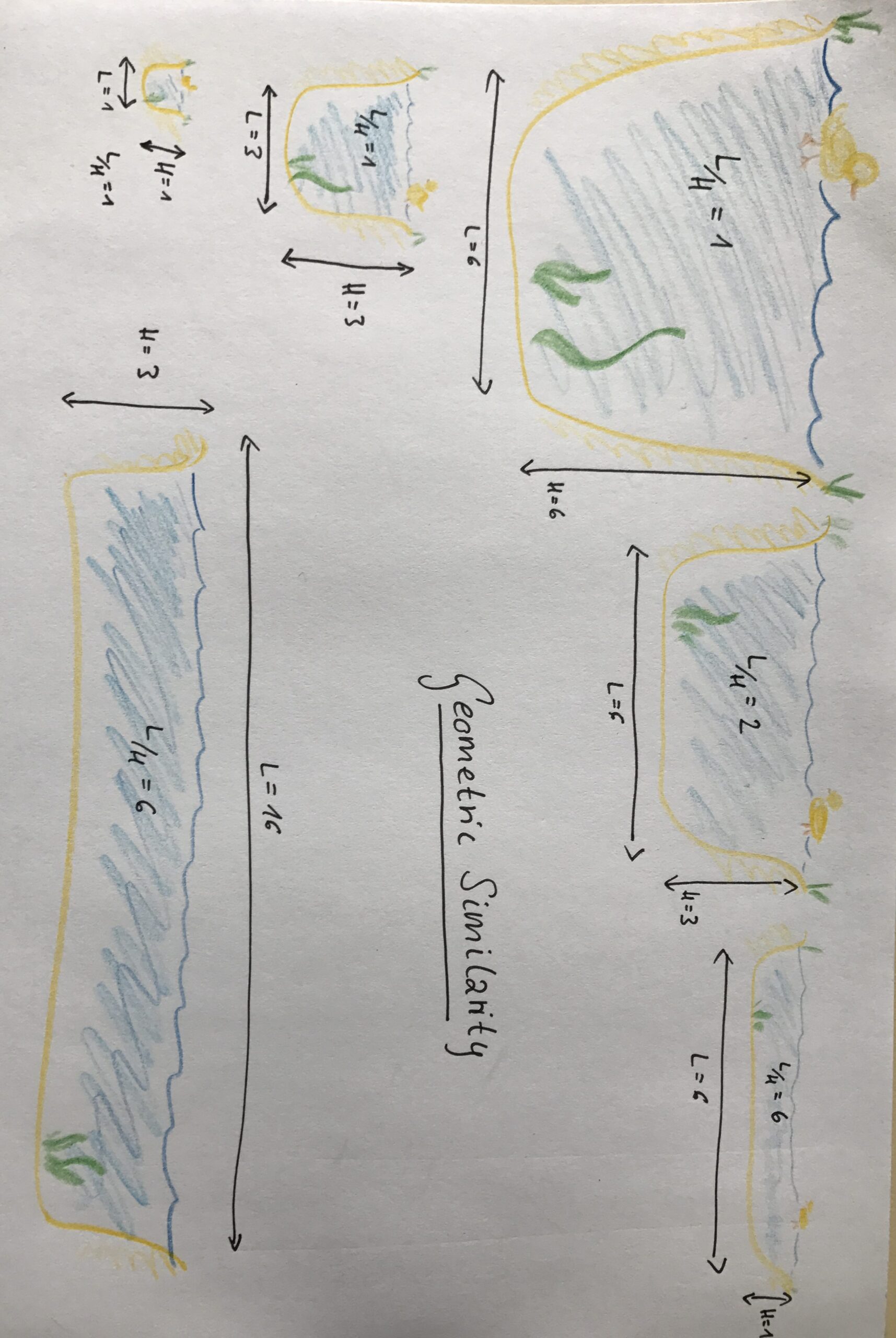
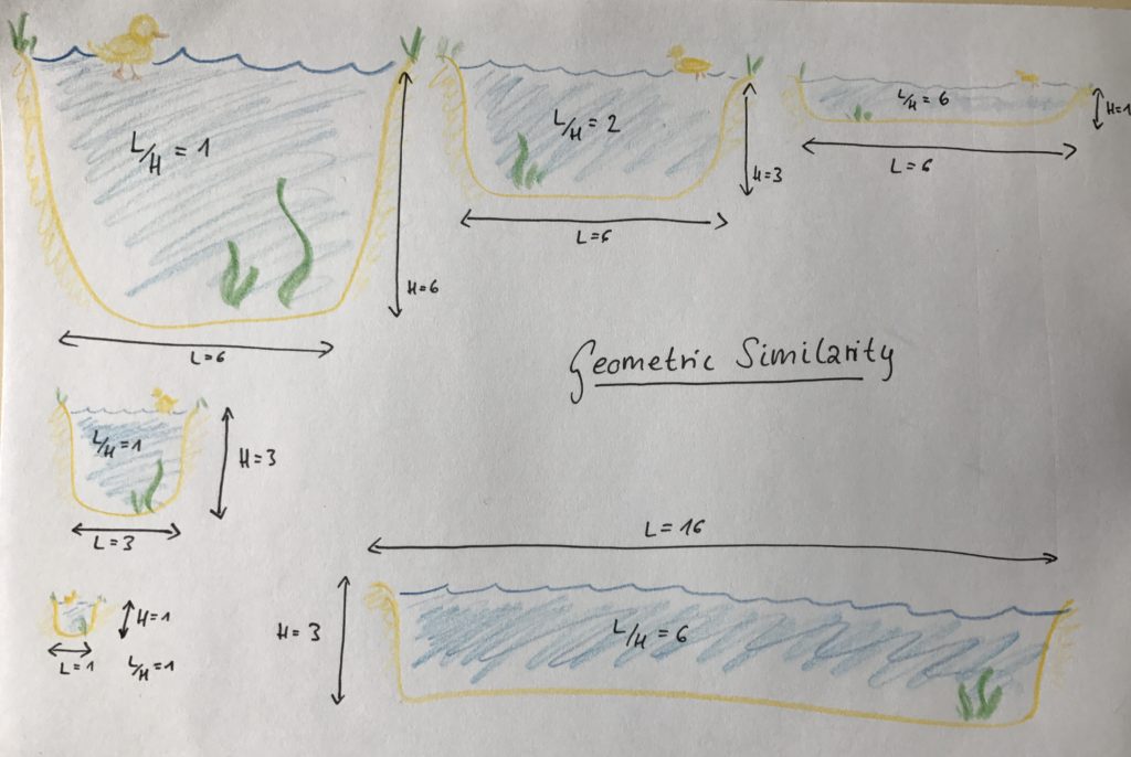
Geometrical similarity
Objects are called geometrically similar, if one object can be constructed from the other by uniformly scaling it (either shrinking or enlarging). In case of tank experiments, geometrical similarity has to be met for all parts of the experiment, i.e. the scaling factor from real structures/ships/basins/… to model structures/ships/basins/… has to be the same for all elements involved in a specific experiment. This also holds for other parameters like, for example, the elastic deformation of the model.

Kinematic similarity
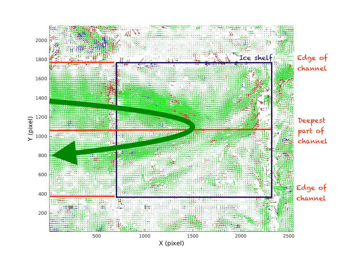
Velocities are called similar if x, y and z velocity components in the model have the same ratio to each other as in the real application. This means that streamlines in the model and in the real case must be similar.

Dynamic similarity
If both geometrical similarity and kinematic similarity are given, dynamic similarity is achieved. This means that the ratio between different forces in the model is the same as the ratio between different scales in the real application. Forces that are of importance here are for example gravitational forces, surface forces, elastic forces, viscous forces and inertia forces.

Dimensionless numbers can be used to describe systems and check if the three similarities described above are met. In the case of the experiments we talk about here, the Froude number and the Reynolds number are the most important dimensionless numbers. We will talk about each of those individually in future posts, but in a nutshell:

The Froude number is the ratio between inertia and gravity. If model and real world application have the same Froude number, it is ensured that gravitational forces are correctly scaled.

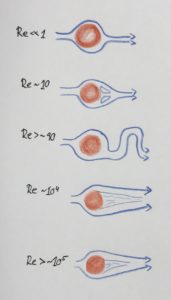
The Reynolds number is the ratio between inertia and viscous forces. If model and real world application have the same Reynolds number, it is ensured that viscous forces are correctly scaled.

To obtain equality of Froude number and Reynolds number for a model with the scale 1:10, the kinematic viscosity of the fluid used to simulate water in the model has to be 3.5×10⁻⁸m2/s, several orders of magnitude less than that of water, which is on the order of 1×10⁻⁶m2/s.

There are a couple of other dimensionless numbers that can be relevant in other contexts than the kind of tank experiments we are doing here, like for example the Mach number (Ratio between inertia and elastic fluid forces; in our case not very important because the elasticity of water is very small) or the Weber number (the ration between inertia and surface tension forces). In hydrodynamic modeling in shipbuilding, the inclusion of cavitation is also important: The production and immediate destruction of small bubbles when water is subjected to rapid pressure changes, like for example at the propeller of a ship.

It is often impossible to achieve similarity in the strict sense in a model experiment. The further away from similarity the model is relative to the real worlds, the more difficult model results are to interpret with respect to what can be expected in the real world, and the more caution is needed when similar behavior is assumed despite the conditions for it not being met.

This is however not a problem: Tank experiments are still a great way of gaining insights into the physics of the ocean. One just has to design an experiment specifically for the one process one wants to observe, and keep in mind the limitations of each experimental setup as to not draw conclusions about other processes that might not be adequately represented.

So much for today — we will talk about some of the dimensionless numbers mentioned in this post over the next weeks, but I have tried to come up with good examples and keep the theory to a minimum! 🙂